

The Traditional Salt Box Home
What a traditional saltbox roof needs to work out, drawn step by step in 3D Home Architect.
3DHA defines a Salt Box structure as being one that has two different pitches to the roof. Their example in the manual shows a one story “Salt Box Like” structure using the two pitch concept. A nice way to show how you can use two completely different pitches on one structure.
But I’d like to thank John Raabe for clearing up a point about Salt Box Homes. A saltbox house usually has a two story portion with a gable roof over it and then a one-story addition covered by an extension of the upper roof down one side. So I will be using the Traditional style in this example using a 12 in 12 pitched roof.
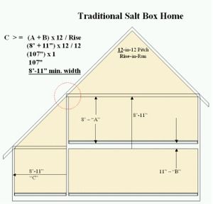
The one dimension you need before you start
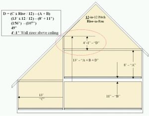
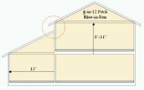
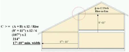
Let’s start by discussing some of the geometry needed to make the roof of a Salt Box building turn out correct in 3DHA. The one dimension you need to know is the MINIMUM distance the side structure needs to extend away from the building. The calculation for that minimum distance is shown in the following picture as “C”. It is calculated by adding the Height of the second floor room (ceiling height) with the height of the floor joists. (8' + 11" in this case) You multiply that sum by 12 (std. run value). Now divide the answer by the Rise Value of your roof pitch. (which happens to be 12 in this case) That would be 107 x 12 / 12, which equals 107". Converted to feet, it would be 8'-11". That distance can be more, but this is the minimum distance. If you use this minimum distance, then your roof rafters will run across the edge of the second floor as shown at the red dotted circle. Later you will see what happens when you make the side structure width larger than the minimum.
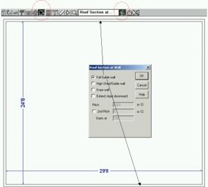
Draw the first floor
Start by drawing a first floor that measures 30' wide by 25' deep. The measurements you see in the example show 29'8" and 24'8". That is because the dimensions are inside to inside. For centerline to centerline, you would have to add 4" to each measurement.
Now tell 3DHA that the top and bottom walls will be gables. Select the Roof tool bar and the Wall Section at Roof tool. (red dotted circles at top) Click on the top wall and the Wall Section at Roof dialog box will open as shown. Click the Full Gable Wall checkbox to add a checkmark. Now click OK. Do the same for the bottom wall.
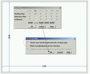
Build the second floor
Now it’s time to build a 2nd story to this house. But before we do you must save your 1st floor plan. Do so now. Name it whatever you would like.
From the main menu choose Window->Show Floors and the Show Floors dialog box will open. Click the Build button under the 2nd floor column and the “New Working Plan” dialog box opens. Leave the option button set at “Derive new 2nd floor plan from the 1st floor” and click the OK button. The 2nd floor will build automatically and you will be taken to that 2nd floor. Note the .pl2 in the title bar indicates that you are on the 2nd floor.
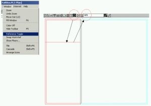
Resize the second floor
Before we change the size of the 2nd floor, let’s turn on the 1st floor reference so we can see the difference between the two floors. From the main menu choose Window->Reference Toggle. Your walls should turn color.
Now resize the 2nd floor. Using the Select tool (arrow), grab the left wall and drag it to the right about 1/3 of the way. (see example) You can check the distance between the outer left wall of the 1st floor (red) and the wall you just moved by selecting the Dimensions tool and dragging a line from the outer edge of the 1st floor wall to the outer edge of the 2nd floor wall. The distance will show up in the text box in the tool bar as you drag. Make sure that distance is equal to or greater than 8'-11". It is 10'-5" in this case. This is the width of the side structure on the floor below.
Build the roof
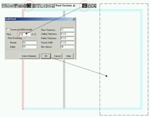
It’s time to build the roof. Select the Roof tool bar and the Build Roof tool. That will open the Build Roof dialog box. All we have to do here is change the Pitch from 6 in 12 to 12 in 12. But notice the 11 inch floor thickness over to the right. That is where we got the 11" floor joist value before. Now click OK and the roof will build. Since you are on the 2nd floor, you will only see the dotted lines that represent the right side of the roof. The left half of the roof is assigned to the 1st floor.
Look at a cross section
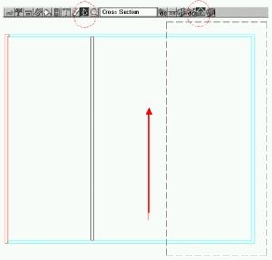
Now let’s view our work to see if we were successful. Select the View tool bar and the Cross Section tool as shown by the dotted red circles in the examples. Drag your cursor (hold down the left mouse button and move the mouse) from bottom toward the top as shown by the red arrow. Release the mouse button and your Cross Section view should appear.
Check the result
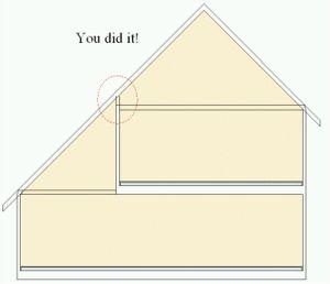
Your results should look something like the picture that follows. If you used the same value for the width of the side structure (10'-5") as I did, then you should notice a short wall like the one inside of the dotted red circle. That short wall is produced any time the width of your side structure is larger than the minimum required value. (in our case that was 8'-11") Also, notice there is no wall separating the main portion of the 1st floor from the side structure. That is because we did not add in the wall. The next two pictures show the wall included. For you to add in that wall, just go to the 1st floor, turn Reference Toggle on, and draw in the wall directly below the outer wall of the 2nd story.
The photos that follow will give you a quick understanding of how these values relate to the creation of the roofs.
How these values relate to the roof
Minimum width by pitch
These are the numbers from the chart on this page, copied cell for cell. Your building department has the final say on any of them.
| Pitch | Inches | Ft.-In |
|---|---|---|
| 12-in-12 | 107" | 8'-11" |
| 11-in-12 | 117" | 9'-9" |
| 10-in-12 | 128" | 10'-8" |
| 9-in-12 | 143" | 11'-11" |
| 8-in-12 | 161" | 13'-5" |
| 7-in-12 | 183" | 15'-3" |
| 6-in-12 | 214" | 17'10" |
| 5-in-12 | 257" | 21'-5" |
| 4-in-12 | 321" | 26'-9" |
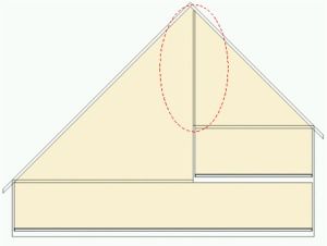
An extreme example
You can see by this extreme example exactly what 3DHA will do to make your model match up to the distances you have entered. By stretching the side building out a great distance to the left, you cause 3DHA to extend the roof upward so the pitch of the roof allows the roof to be completed.
Where to go from here
- See how roof slope is set and extended in the same program.
- Read the rest of these 3D Home Architect notes.
- Ask about roofs in our discussion forum.