
- Welcome to CountryPlans Forum.


Recent posts
#1
Referral Links / Re: Wall Plugin for SketchUp
Last post by Medeek Engineering - Yesterday at 12:00:23 AMVersion 4.6.4 - 06.15.2026
- Added a "deck" option to the railing module.
Note that when Railing Type is set to "Deck" there will typically be a cap rail along with an upper and lower rail. The upper and lower rail provide the support for the balusters or pickets.
I will probably need to enable an option to disable or turn off the cap rail.
#2
Owner-Builder Projects / Re: Okanogan 14x24 by a lurker...
Last post by OlJarhead - June 15, 2026, 06:27:20 PMHere we go!
#3
Referral Links / Re: Wall Plugin for SketchUp
Last post by Medeek Engineering - June 14, 2026, 02:17:06 PMVersion 4.6.3 - 06.14.2026
- Enabled open treads for curved stair assemblies.
- Enabled handrail fittings for curved stair assemblies.
- Added six additional parameters into the curved stair sub-menu for handrail extensions and upper fitting rail drops.
- Enabled handrail posts for curved stair assemblies.
- Enabled OTP, CUT, and VERTICAL (PTP) handrail options.
- Added a vertical offset parameter for top posts.
#4
Referral Links / Re: Wall Plugin for SketchUp
Last post by Medeek Engineering - June 14, 2026, 01:15:37 PMI've been also thinking about the framing that goes under these stairs and it seems to me that the methods are as varied as there are carpenters. I could provide a basic curved wall framing as shown in the screenshots below but I don't know how much use this would be to anyone as they will probably frame it differently, thoughts?


#5
Referral Links / Re: Wall Plugin for SketchUp
Last post by Medeek Engineering - June 10, 2026, 04:54:51 AMVersion 4.6.2 - 06.10.2026
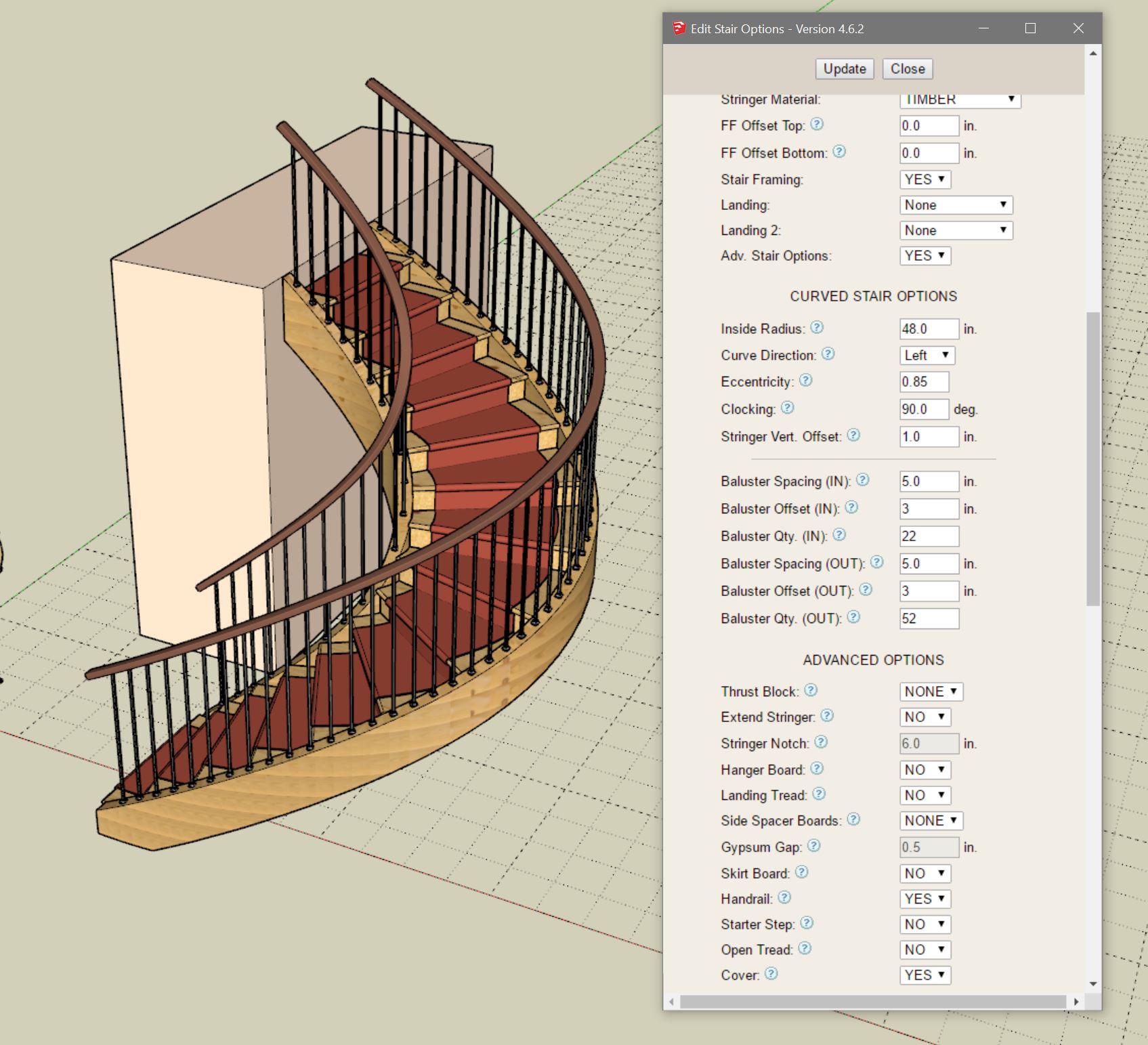
- Added balusters and baluster shoes for all curved stair assemblies.
- Added separate baluster spacing, offsets and quantities for inner and outer handrails of curved stair assemblies.
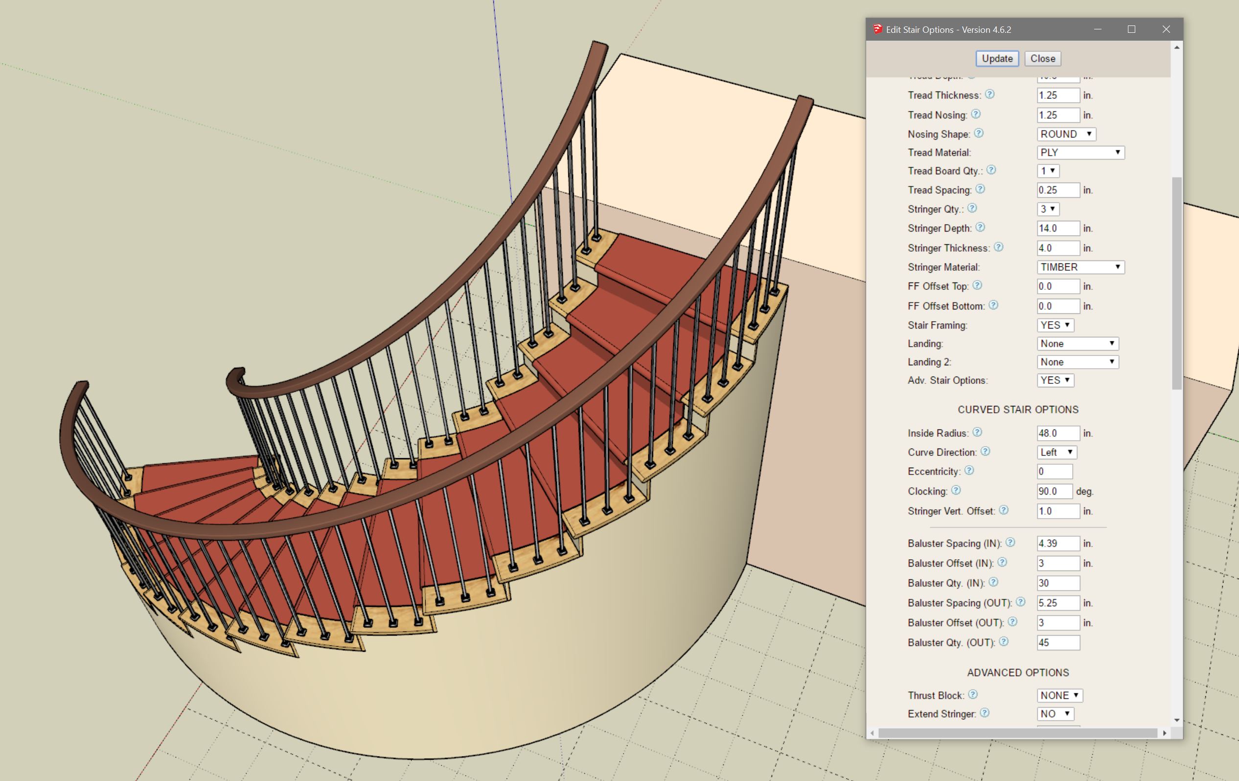
With circular stairs it is possible to carefully control the spacing of the balusters so that a specific number of balusters lands on each tread (two on the inner and three on the outer). However with elliptical stairs the tread arc length may vary significantly so this may or may not be as controllable. I may need to come up with a different way to space balusters on elliptical stairs.
Note that in the second screenshot where the balusters are attached to the closed stringer this is not an issue.
Each side can be adjusted separately with the addition of the six new parameters within the Curved Stair Options sub-menu. This level of granularity is required for curved stairs at the expense of making the menus a bit longer.
- Added balusters and baluster shoes for all curved stair assemblies.
- Added separate baluster spacing, offsets and quantities for inner and outer handrails of curved stair assemblies.
With circular stairs it is possible to carefully control the spacing of the balusters so that a specific number of balusters lands on each tread (two on the inner and three on the outer). However with elliptical stairs the tread arc length may vary significantly so this may or may not be as controllable. I may need to come up with a different way to space balusters on elliptical stairs.
Note that in the second screenshot where the balusters are attached to the closed stringer this is not an issue.
Each side can be adjusted separately with the addition of the six new parameters within the Curved Stair Options sub-menu. This level of granularity is required for curved stairs at the expense of making the menus a bit longer.
#6
Referral Links / Re: Wall Plugin for SketchUp
Last post by Medeek Engineering - June 09, 2026, 03:13:47 AMBalusters on curved staircases is a bit challenging, I'm not going to lie. My algorithm(s) are mostly working, and I think, as I suggested in my previous postings, I will need to add in some additional (curved stair specific) parameters. At this point I really hate to add more parameters to these already substantially bloated menus. Too many settings and options tend to overwhelm the casual or new user, but at the same time we need enough controls or knobs to fully adjust these assemblies, its a bit of a trade off I guess. As the Japanese say "Shikata ga nai" (仕方がない).
This screenshot is of a "circular" curved staircase with 1/2" square balusters and baluster shoes. As you can see the baluster spacing is not quite right for either side (inner and outer handrails). To get exactly 2, 3 or 4 balusters per tread one will need to carefully and probably iteratively adjust the spacing. Since these arc lengths won't be nice even numbers the exact spacing number will be some fractional value. I've got some ideas on this to make things a bit easier for the user to compute these exact spacings but I need to experiment with it further.
Its funny how when I start down one of these rabbit holes I don't usually don't know the full solution to the problem or even fully understand the problem itself. But as I slowly unravel and work my way through one of these problems it ultimately becomes clear and then along the way I seem to always find better ways to address the problems that I encounter.
#7
Referral Links / Re: Wall Plugin for SketchUp
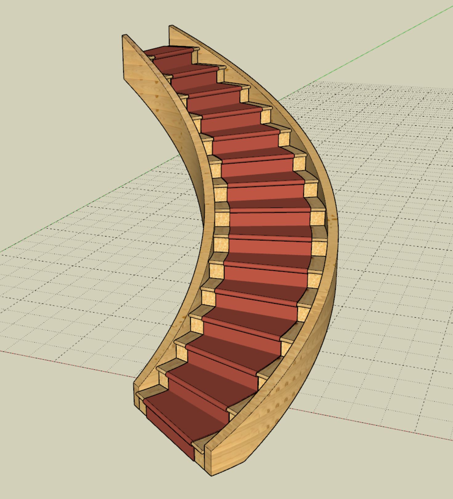
Last post by Medeek Engineering - June 07, 2026, 12:56:19 AMVersion 4.6.1 - 06.06.2026
- Added tread covers, carpet and stair runners for all curved stair assemblies.
- Enabled a "code" clearance envelope for curved (elliptical and circular) stairs.
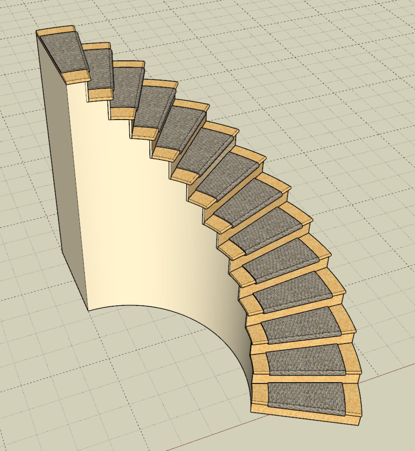
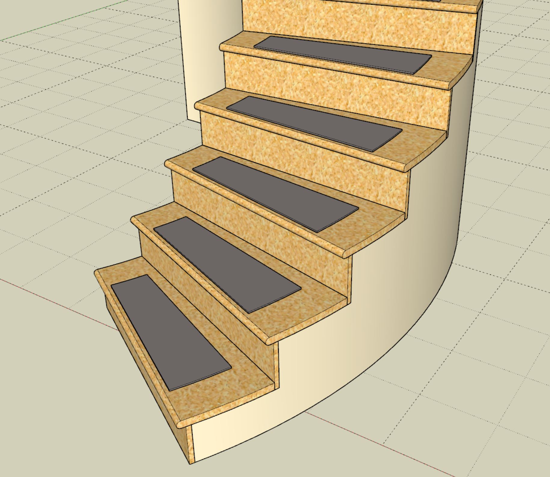
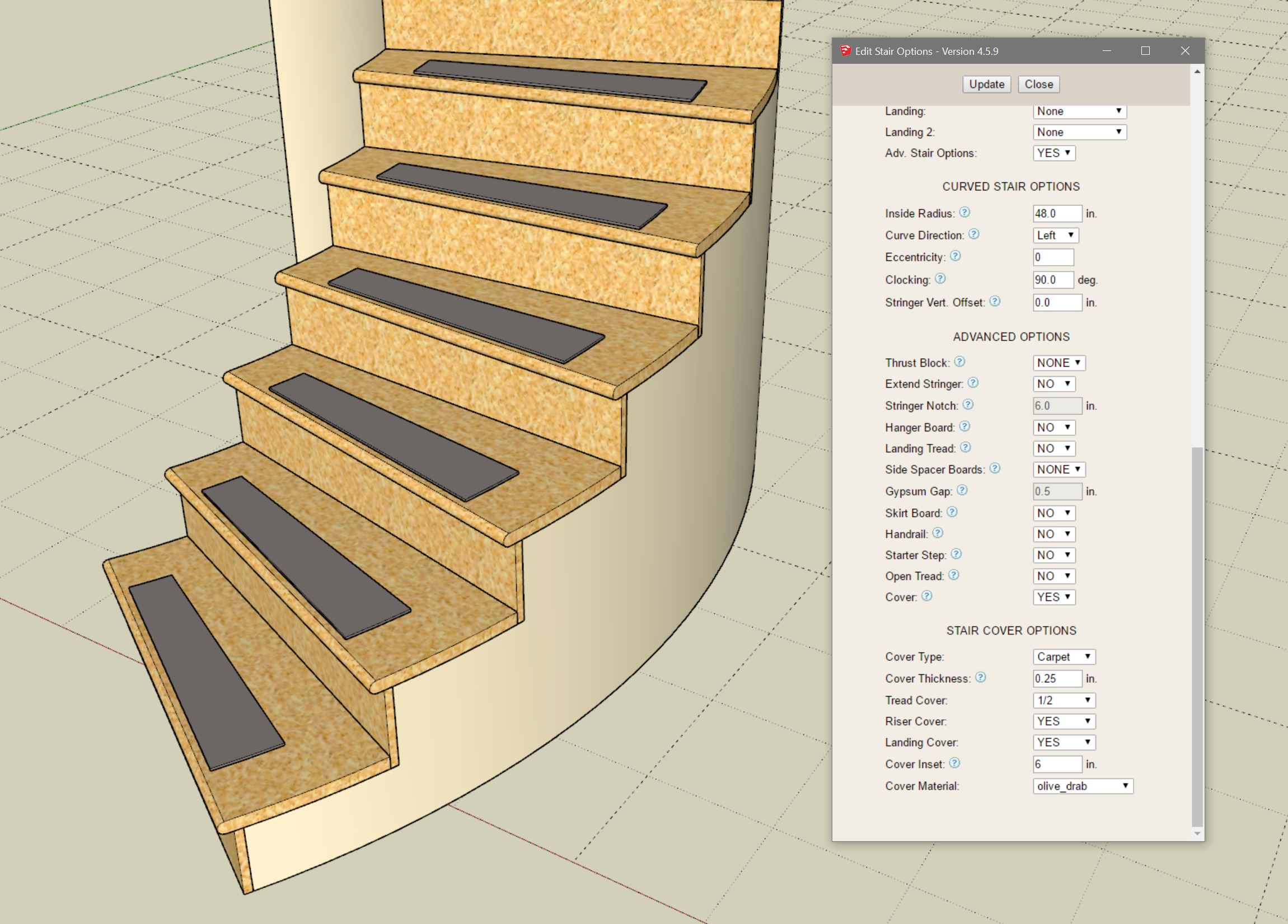
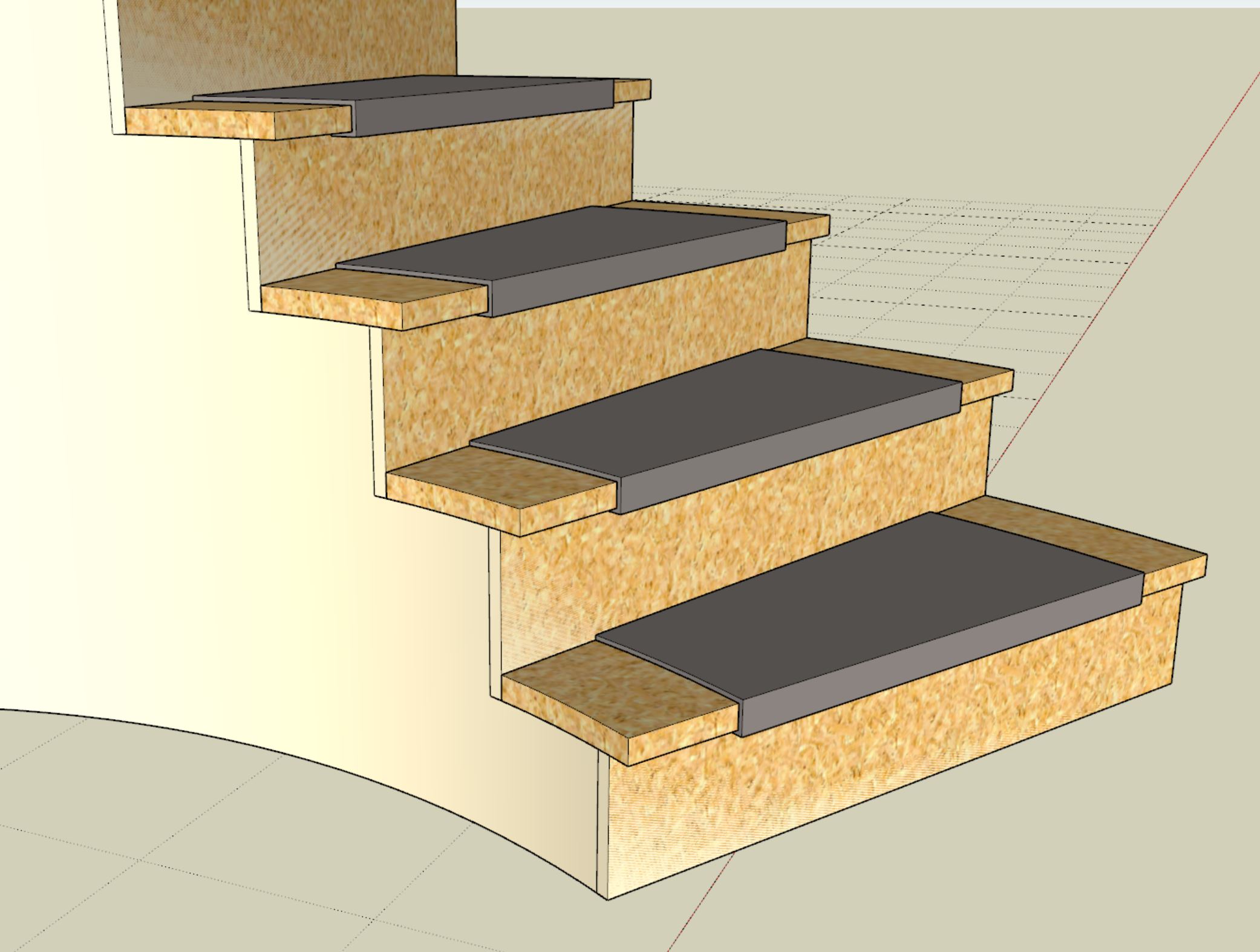
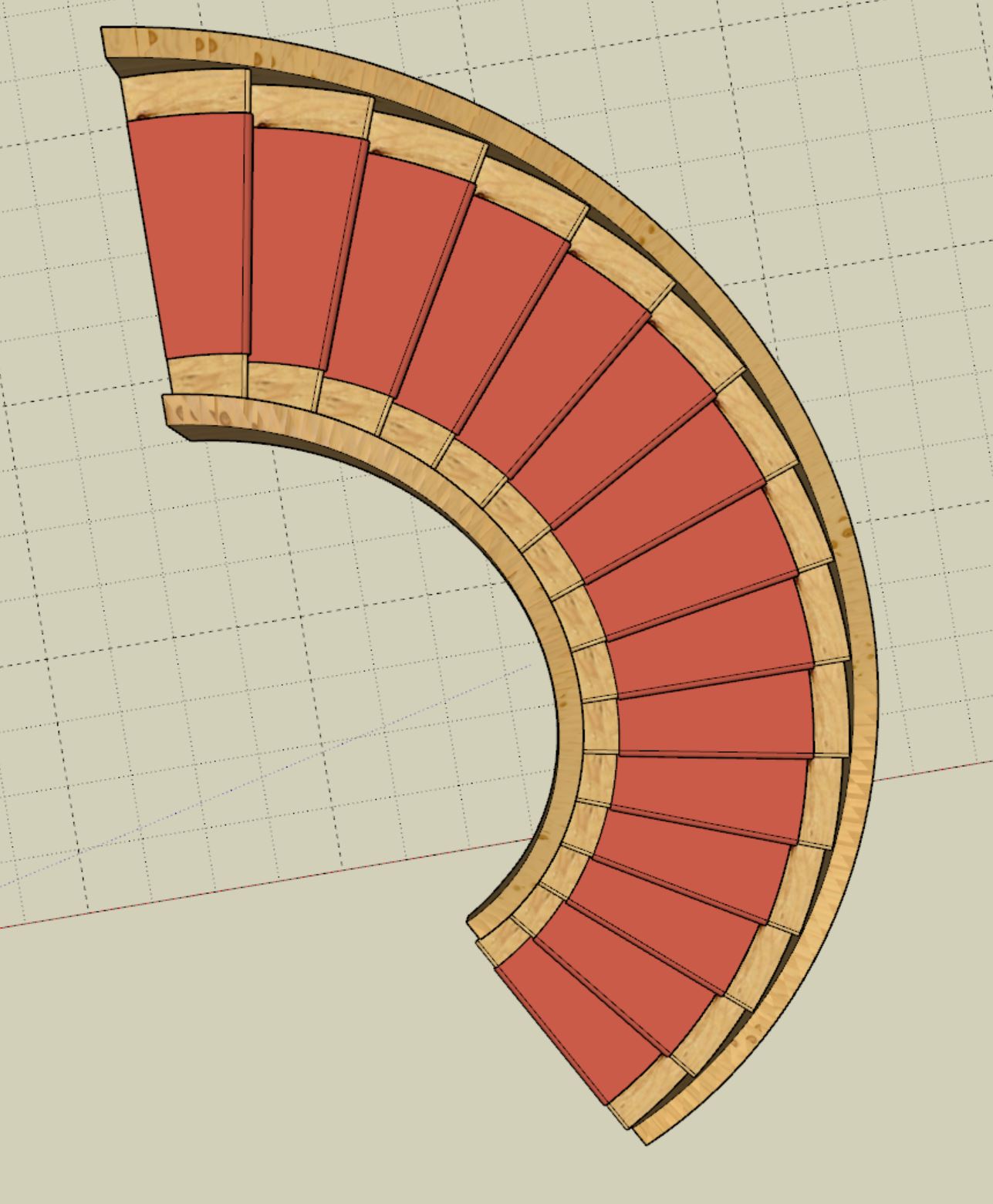
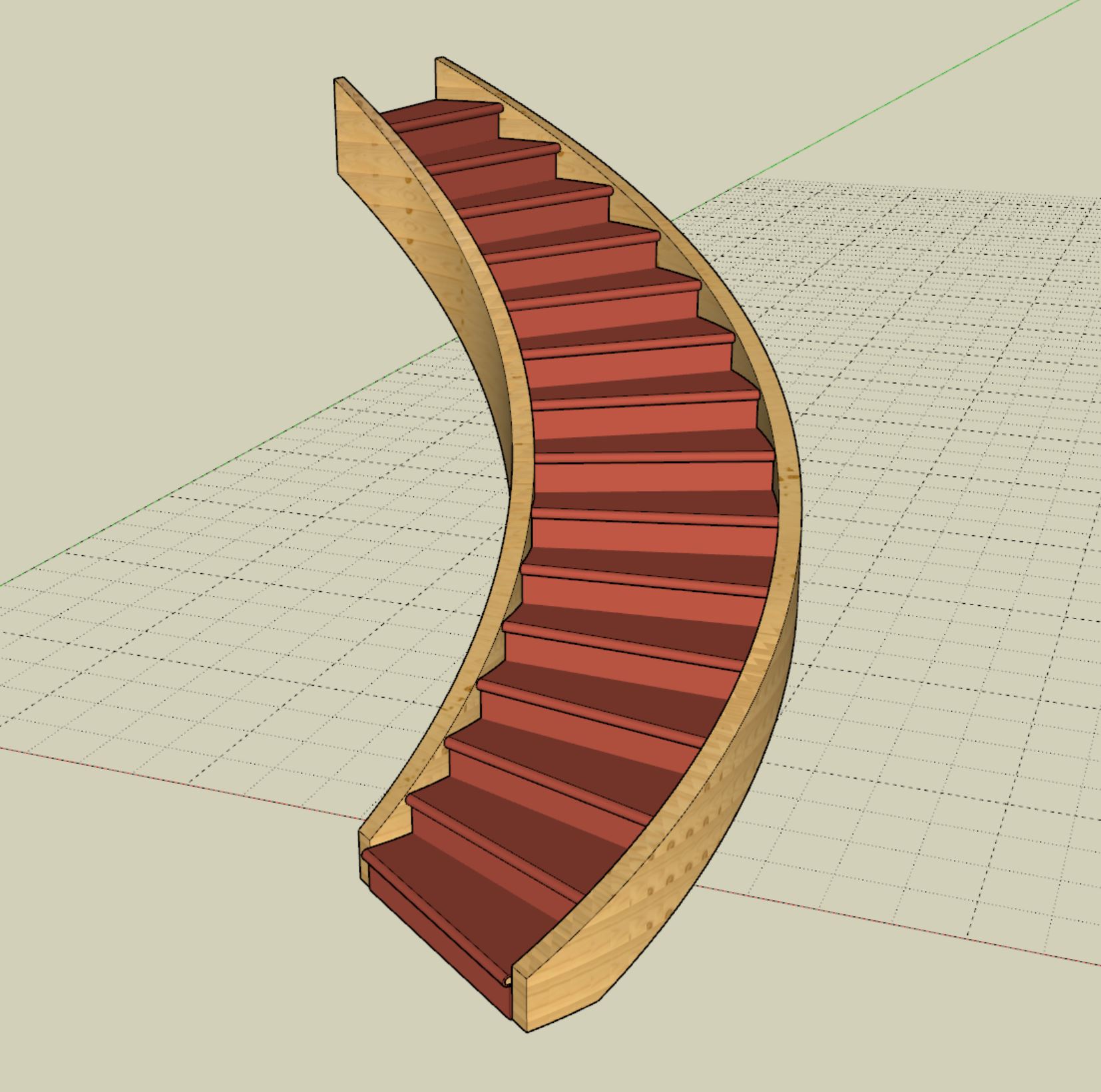
- Added tread covers, carpet and stair runners for all curved stair assemblies.
- Enabled a "code" clearance envelope for curved (elliptical and circular) stairs.
#8
Referral Links / Re: Wall Plugin for SketchUp
Last post by Medeek Engineering - June 06, 2026, 07:47:44 AMMedeek Wall: Version 4.6.0b - 06.06.2026
- Added handrails to curved stairs.
- Fixed a bug with labels for railing labels with metric templates.
- Added handrails to curved stairs.
- Fixed a bug with labels for railing labels with metric templates.
#9
Referral Links / Re: Wall Plugin for SketchUp
Last post by Medeek Engineering - June 04, 2026, 07:57:56 PMAfter mucking around with the follow me API call and a few other algorithms I decided to strike out on my own yesterday, and with a little help from ChatGPT and quite a few iterations I was able to finally generate the closed helical stringers. Using the same principle and by rotating the profile I am now able to generate a similar mesh for the handrails. These are high poly but it does look great and we now have eliminated the twisting issue that I had never resolved using other methods. So a major step forward.


#10