
- Welcome to CountryPlans Forum.


Recent posts
#1
Referral Links / Re: Medeek Floor Plugin
Last post by Medeek - Yesterday at 11:37:01 PMVersion 0.9.6 - 09.19.2024
- Fixed a bug with metric floor presets.
- Fixed a bug with the insulation module.
- Fixed a bug with metric floor presets.
- Fixed a bug with the insulation module.
#2
Owner-Builder Projects / Re: Pier and Beam for 20x32 sh...
Last post by Don_P - Yesterday at 04:38:26 PMI think you're being optimistic but let's see...
A 4x6 is I'm assuming a Southern Pine timber in #2, at 8' span. It is going to max out at 1650 lbs uniformly distributed along its length.
hmm, lets look at a triple 2x6 in #2 SYP just to compare...2000 lbs uniform load.
8'x8' of wall at 10 psf reduces the capacity by 640 lbs leaving the 4x6 with about 1000 lbs capacity to carry roof and floor.
1000 lbs/8' beam span=125 lbs beam capacity per lineal foot remaining
A roof here, live+ dead load is 40 psf, a floor LL+DL=50 psf so combined 90 lbs per square foot.
125 plf capacity/90 psf=1.38' of joist + rafter span can be supported by that beam.
That was residential floor loading, a shop tends to get heavier as time goes on.
#3
Owner-Builder Projects / Re: Pier and Beam for 20x32 sh...
Last post by Tillman Schimmel - Yesterday at 04:04:54 AMBased on the weight it needs to hold (roof weight, snow loads, etc.), a 4x6 beam can usually span 8 to 10 feet. When building a shop, the load may be greater, especially if there is a loft or a heavy roof.
#4
Referral Links / Re: Medeek Floor Plugin
Last post by Medeek - Yesterday at 02:11:13 AMI have had two requests now for metal bridging or bracing so I took about an hour and modeled up a Simpson TB27 between 2X10 joists @ 16" on center. It actually looks really nice:


However some things immediately jumped out at me:
1.) I based my TB27 off of the ICF file on Simpson's website so it is dimensionally accurate, however to do that takes quite a bit of time. Modeling like this is fun but very time consuming and one thing I never have enough of is time.
2.) This is the TB27 configured for 2X10's on 16" centers, now think of all the other permutations (including I-Joists). To make this look right would require a preconfigured component for each case. The number of permutations is at least 130 or more.

3.) If you also consider custom offsets of specific joists then it gets even more crazy.
My thinking is that if I do want to enable something like this it will need to be less detailed geometrically (just a basic representation) and drawn on the fly using an algorithm that checks joist depth and spacing. Rather than specify the exact part number (ie. TB20, TB27, TB30 etc...), just specify that it is metal bridging.
However some things immediately jumped out at me:
1.) I based my TB27 off of the ICF file on Simpson's website so it is dimensionally accurate, however to do that takes quite a bit of time. Modeling like this is fun but very time consuming and one thing I never have enough of is time.
2.) This is the TB27 configured for 2X10's on 16" centers, now think of all the other permutations (including I-Joists). To make this look right would require a preconfigured component for each case. The number of permutations is at least 130 or more.
3.) If you also consider custom offsets of specific joists then it gets even more crazy.
My thinking is that if I do want to enable something like this it will need to be less detailed geometrically (just a basic representation) and drawn on the fly using an algorithm that checks joist depth and spacing. Rather than specify the exact part number (ie. TB20, TB27, TB30 etc...), just specify that it is metal bridging.
#5
Referral Links / Re: Medeek Floor Plugin
Last post by Medeek - September 18, 2024, 07:49:21 PMVersion 0.9.5 - 09.18.2024
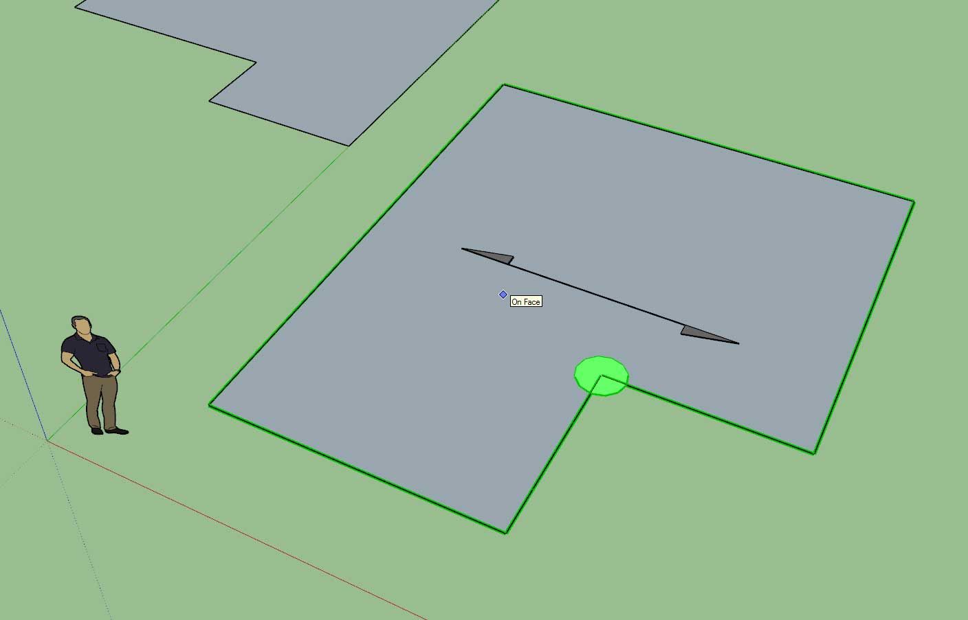
- Added a joist direction arrow to the draw floor tool.
- Added a "debug mode" parameter to the General tab of the Global Settings.
- Fixed a bug with deck board placement.
- Fixed a bug with the deck board offset parameter.
- Added a joist direction arrow to the draw floor tool.
- Added a "debug mode" parameter to the General tab of the Global Settings.
- Fixed a bug with deck board placement.
- Fixed a bug with the deck board offset parameter.
#6
General Forum / Re: Gable end framing -- hinge...
Last post by Don_P - September 18, 2024, 12:05:03 PMThe WFCM does have a lot of good tables and details... in a mind numbing format  Don't forget the commentary if you get stuck, sometimes it clears it up.
In most of those engineering short courses at the nearby land grant U there's one or two builders in a room full of design pro's and inspectors. Among them are also folks that see more fail examples in the field than I ever will with my head down building one at a time. I'm a fan of cross training and these folks do a good job. This is a flier from one earlier this year;
Structural Design Topics in Wood Construction | Continuing and Professional Education | Virginia Tech (vt.edu)
But also track down whatever is of interest, APA does training for engineered wood products, NFBA for post frame building, etc. Most of those have webinars on their websites as well... I've been watching some from the gypsum people on fire assemblies lately for the current project.
Thinking of a wall... stand the building up on end. Park a Volkswagen in the middle of the now horizontal wall, get out and walk around on the wall. That's pretty much gale force wind thinking. Now look at the connections holding your "floor" up. That's actually how good they should be. It is very easy on a calm sunny day to forget about the forces and direction those forces come from on a bad day.
Balance that with longevity, I really like large overhangs that keep water away from the walls too.
Don't forget the commentary if you get stuck, sometimes it clears it up.In most of those engineering short courses at the nearby land grant U there's one or two builders in a room full of design pro's and inspectors. Among them are also folks that see more fail examples in the field than I ever will with my head down building one at a time. I'm a fan of cross training and these folks do a good job. This is a flier from one earlier this year;
Structural Design Topics in Wood Construction | Continuing and Professional Education | Virginia Tech (vt.edu)
But also track down whatever is of interest, APA does training for engineered wood products, NFBA for post frame building, etc. Most of those have webinars on their websites as well... I've been watching some from the gypsum people on fire assemblies lately for the current project.
Thinking of a wall... stand the building up on end. Park a Volkswagen in the middle of the now horizontal wall, get out and walk around on the wall. That's pretty much gale force wind thinking. Now look at the connections holding your "floor" up. That's actually how good they should be. It is very easy on a calm sunny day to forget about the forces and direction those forces come from on a bad day.
Balance that with longevity, I really like large overhangs that keep water away from the walls too.
#7
General Forum / Re: Gable end framing -- hinge...
Last post by rothbard - September 18, 2024, 11:14:27 AMThat WFCM keeps coming in handy, much appreciate the notes. Looks like I can derate to ~0.44x based on 8" overhang yielding more like 130 lbs-force / 16" o/c outrigger @ 110 mph, well within what simpsons connectors can handle.
Reality does have a cold way of smacking classroom pontification in the face, as Mike Tyson once said in so many words. That probably helped solidify that knowledge in a unique way. Curious what kind of class this was, something on structural engineering?
I am definitely blocking between the riggers in any case to reduce the chance of falling through while "hanging on by my toenails"
#8
Referral Links / Re: Wall Plugin for SketchUp
Last post by Medeek - September 17, 2024, 10:42:36 PMVersion 3.7.1 - 09.17.2024
- Added a vertical offset parameter for in-wall column king studs.
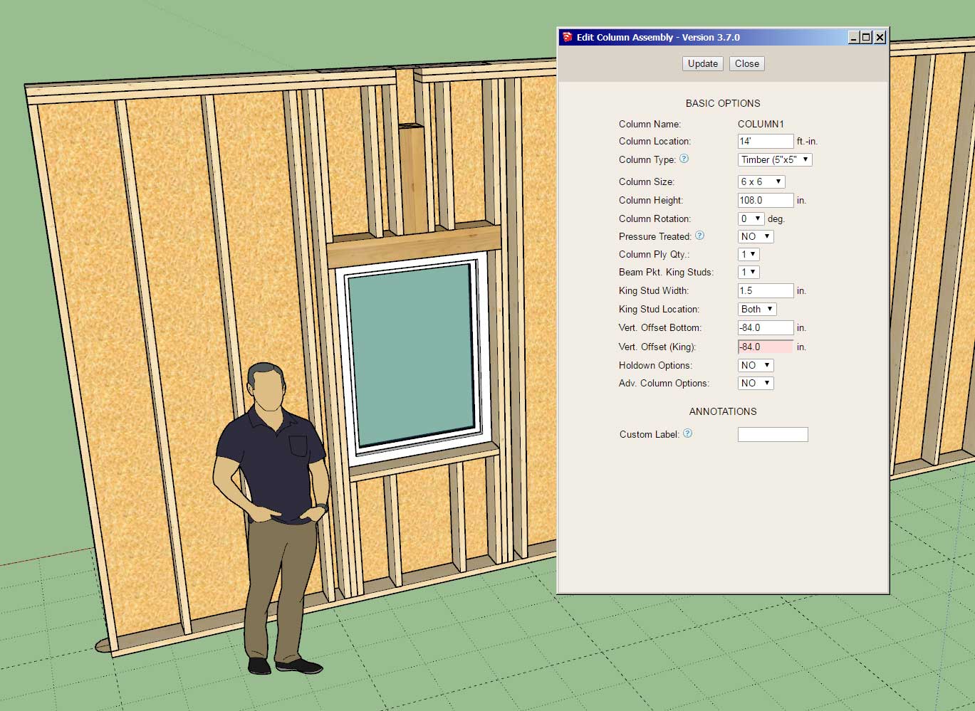
In the case where you have a beam pocket and king studs over top of a door or window this update is critical. Previously the king studs would simply project to the bottom plate in the wall passing through the opening. Now you can utilize this extra parameter to vertically offset these king studs the same way the column itself is offset. Note that the offset can be both positive or negative or zero (default)
- Added a vertical offset parameter for in-wall column king studs.
In the case where you have a beam pocket and king studs over top of a door or window this update is critical. Previously the king studs would simply project to the bottom plate in the wall passing through the opening. Now you can utilize this extra parameter to vertically offset these king studs the same way the column itself is offset. Note that the offset can be both positive or negative or zero (default)
#9
General Forum / Re: Gable end framing -- hinge...
Last post by Don_P - September 17, 2024, 08:40:27 AMI can't say I've checked uplift this well but here is the page for exposure B from the code referenced WFCM, Wood Frame Construction Manual. In a class the professor noted that most roofs peel from the bottom corners. If you look at the wind/ sheathing loads tables in chapter 3 of the IRC those are the wind concentration areas. It's whipping around the corner and getting pinched by the slope as well. I had to comment to the room full of smart people, I'm usually facing down and hanging on by my toenails while building that bottom corner. I could see the light bulb come on in several design pro's who had only built virtually. However, personal discomfort doesn't change reality, make sure they are built well.
The hold down could be accomplished other ways, for instance a timber screw that has the needed capacity in its tables down to a plate that has sheathing connection capacity to maintain the uplift load path.
The "usual" cantilever rule applies for "L", "twice as much framing inboard as outboard".
If I'm having to slide the 1st rafter over into what would be the 2nd bay it needs to be doubled... but! put the outboard rafter in, shoot on the lookouts through from the backside then put the 2nd rafter on the inboard side and nail it to the 1st rafter well. Beyond 2' outboard or in high snow that inboard connection starts to need upside down joist hangers or some better connection.
We block between lookouts over the wall, it locks and fireblocks the assembly. Ah, looking at it that would be the "required blocking"
#10
Referral Links / Re: Medeek Floor Plugin
Last post by Medeek - September 16, 2024, 06:40:36 PMTutorial 2 - Joist Hangers (19:57 min.)