

How to Frame a Gambrel Roof for the 2nd Story
An owner designed cabin in mid Tennessee with a site built gambrel roof, balloon framed and put together with screws instead of nails.

Photos and comments from owner Jim Redic (note: later photos and updates are below)
The photos above and below are of a project my wife and I (both in our 60’s) are working on for our daughter. The site is located in mid Tenn.. and we only get up there a few hours each month. Originally we were just going to help make a footing for a 16'x20' prefab shed -- to be used as weekend retreat. But soon the footing became a full basement, and the prefab shed project became a design (by me) and build (my wife and me) custom home.
Since we are doing all the labor, I chose ‘balloon framing’ because studs are easier to lift than entire walls -- and it suits the Gambrel roof. For additional strength, the studs were changed to ‘posts’ made from a 10' 2x6 attached to a 12' 2x4. Since using a hammer fatigues me pretty quickly, and those nail guns look so dangerous and clumsy; this project has been totally put together with screws -- much faster for me -- very secure -- and can be easily disassembled if needed. Most of the screws were installed using a regular 3/8 reversible Dewalt. For close quarters I have a 90 degree gear head drill. Several lbs of Simpson brackets have also been used. Since we knew it would take us a long time to get ‘dried in’, all the wood has been coated with spar varnish before assembly.
The Gambrel roof was designed to be fully symmetric -- half of a octagon. Each ‘straight leg’ is 6' -- one and a half sheets of plywood laid sideways. I’m trying to talk my daughter into using 1x6 T&G instead of plywood. I can manage the ‘racking’ concern. Flared eaves will be added to the roof rafters next. My daughter and her husband get to come up only a few hours on some weekends; but they did make and coat all the rafter pieces. I would assemble them on site (using a jig form), and then when they were there to help we would all lift them in place. You can see a couple of trusses waiting for some extra muscle in the picture above.
We have actually progressed a bit further than these photos show, but we’ve now shut down for the winter. The photo below was taken later (after the lifters were done).
Here are some last minute notes from Jim:
- I forgot to mention that the first floor (untreated) wood was painted with acrylic latex -- I wish I had used spar varnish throughout.
- The right angle gear drill is a Milwaukee 0375-1.
- The handiest tool I found was a Wilton economy “L clamp” (#612). I ended up buying 6 of these. They are super quick to use. 11 1/2" throat. $50+ at WWGrainger. Great for the 1-person crew.
- The 2x6 ridge poles are now in place. They overhang 2' feet on each end. And we’ve trimmed some of the excess 2x4’s that extend upward beyond the rafter assembly.
- The joist “toe screws” are long enough to go through the ledger plate and into the stud posts. For some of the longer screws, I would often pre-drill an 1/8" pilot hole w/ a 6" drill bit.
- If I had known in the beginning that I was going to be the designer/builder, the basement would have been wide enough to accommodate full 16' long 2x10 joists -- this would have helped when laying in the staircase (which is rather tight!).

Comments from John
Jim is exploring several interesting ideas here. Framing using a screw gun instead of a hand or air hammer has some real merit. Especially for those of us with hands that aren’t as nimble as they used to be. Screws are a bit more expensive but the holding power is greater and they can be reused if put in wrong whereas lots of nails are wasted. Also, I like the idea of sealing the frame if it will be exposed during the winter. Jim will have to let us know how that idea works out next spring.
Jim has been creative with his framing as well. Notice the gaps where the legs of the roof sections are gussetted? I assume there will be a ridge type board installed there and at the peak. As I understand it, Jim will expose the rafters (and maybe the wall framing?) to the interior and have 1x6 T&G sheathing on the outside. He will put any insulation on the outside of this and metal roofing on skip sheathing that can be nailed down into the rafters. If this building is not in heavy wind or earthquake country the owner can probably brace with metal straps on the outside of the sheathing and under the insulation (another use for the screw gun). Jim could also put up siding over skip sheathing for the walls and have a long-lasting “rain barrier” type of wall system. The only problem with this exterior insulation system is that getting to high R-values will be expensive and troublesome as the foam gets thicker.
Notice how the floor is supported off the walls with a ledger. Someone was asking about this on the discussion forum just the other day. Below are a few additional photos that Jim sent:


Update: October 2003

Update: Spring 2003
Jim’s report:
2003 started out slowly for us, like for others, because of all the spring rain. Finally work began again, but as slowly as ever -- remember, we are (very) senior citizens -- and this is, after all, just a hobby project. In addition, the afternoon naps, that I now require, are longer this year than last year.
The practice of prepainting the structural wood has yielded mixed results. The wood that was double-coated did fairly well, but the single-coated surfaces showed weathering pretty badly. I would also suggest that spar varnish is too expensive for this use.
The Gambrel roof design, so far, is satisfying -- yielding more usable floor space than most loft designs -- remember that I factored in a generous knee wall to make this so. Balloon framing has many merits -- rigidity, ease of assembly, etc -- I endorse its use for the inexperienced such as myself. The Gambrel roof requires attention to flashing detail to prevent rain water leaks. You will see flashing in many of the attached photos. One photo focusing on the flashing bending “machine”.
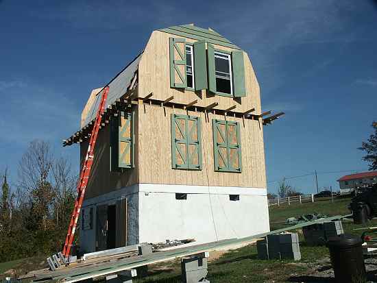
One of your posters inquired about the work platforms (catwalks) that I installed at the top floor level. The catwalk was originally installed at an angle, keeping the worker (hey, that’s me!) leaning inward toward the building. It was later lowered to the current horizontal position -- for less siding installation interference. Both versions are seen in the photos. When the support 2x4’s are removed, a trim cover will be installed.
You can see that the material removed from the window spaces was used to make permanent in-place shutters. This is a very comforting feature in a area that has its share of high winds. They will also give privacy and sun control.
The photos below show the project as it is -- waiting for a metal roofing support system, waiting for the rear porch to be begun, waiting for more time to work on it.


Where to go from here
- Read the forum thread on balloon framing and gambrel roofs for loft space, where Jim came back years later to explain the outward thrust a knee wall adds to a gambrel roof.
- Visit the CountryPlans home page.
- Browse the Owner Builder Gallery for stories of other projects.
- Ask general questions about building cabins and small houses in our forum.