|
THE PHYSICAL MODEL While home design software makes it easy to view your home design in the 3rd dimension (a Virtual Model), that isn't always good enough. Building a physical model helps many people better understand what they are going to get when the project is complete. |
That model can be used to determine how shadows will show thru windows or how much light will be added to a room by including a skylight. (3DHA v3.0 does not include skylights or shadows) But you can use 3DHA's unique features to help you build the pieces that you will need to build an accurate physical model. I will be using a simple design with gable ends and hip roofs in the front and rear. |
|
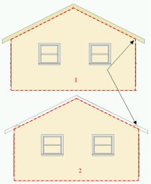
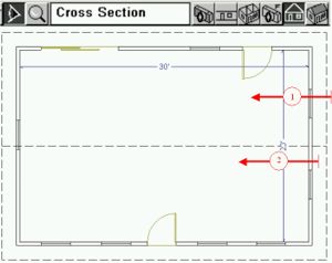
We will start off by showing the best way to create the walls of your model. ALWAYS use the CROSS SECTION tool as shown in the next picture! First I would like to show that capturing the gabled end of a house is very easy. View #1 starts the camera outside of the facia to the roof and is dragged toward the house. The Cross Section view below (#1) shows the facia because it was in the field of view of the camera. Now notice that view #2, which starts inside the facia, does not include the facia in the Cross Section view. You now see a small piece protruding above the wall. Don't worry about this as it is the ceiling joist (clipped) and is not a part of the wall. |
 |
|
|
So you can see that whether or not you drag the Cross Section tool from outside the facia or inside, you can easily figure out how to cut the gabled wall. Now print out this view at the scale you want, paste it on your model material, and cut out the wall where I have placed a dotted red line. (at 1/4 scale, a 6" thick wall would require 1/8" thick material. 1/8" foamboard is generally what you would use.) |
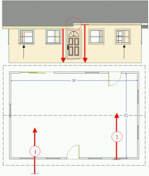
| A wall with a hip roof is not quite as simple because the hip roof extends down over the wall in Cross Section view. Here is where you will determine the best place to start a Cross Section view from. The picture that follows shows one house with two different views. View #1 starts from outside the facia and view #2 starts from just outside the surface to the wall. In Cross Section, you see that view #1 (left side) shows the height of the wall to be the same as the top of the window. How can that be? Where is the header above the window? You just can't see that section of the wall because it is hidden behind the roof section. But view #2 eliminates the roof section because it starts just outside of the wall surface. Now you see the real height of the wall. You can also see that the window trim shows up completely on the left, but only the outline of the window frame is visible on the right. That is because you started view #2 less than 3/4" away from the wall and you cannot see the face of the trim because it is behind the camera plane. |
|
|
|
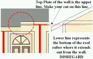
A section of the previous picture has been blown up for a
better understanding of where to cut. The dotted red circle shows the
difference between the two heights.
But view #2 has two black lines near the top of the wall. Which one do we use? The lower of the two lines is actually the bottom of the roof section, cut in cross section. Disregard this line. The upper line is the top of the wall, (top plate), but below the ceiling joists. Use it to cut your wall section. |
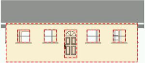
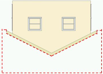
| The full wall section is shown next. The dotted red lines have been added to show where you would cut to get a good model wall. Make your window cuts inside the frame, only cutting out the glass. Use a sharp razor blade or cutting knife to get clean, accurate edges. |
|
|
|
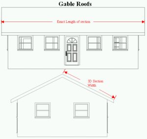
Roofs are a bit tougher. But gabled roofs are the easiest,
so we will start with the same gabled roof on the model we have been
using. Each roofing section will need to be created. But
because the roof is not flat and actually rises from the model, you
cannot use the Plan View as a template for your roof. So again we turn
to our Cross Section views. The two examples shown in the previous
picture show how to determine the length and width of a gabled roof
section. Create these views, print to scale, measure the length
and width, transfer the measurements to your building material, and cut
out your roof sections.
The length is the same as in Plan View, but the 3D Cross Section width is the important measurement that varies from the Plan View! |
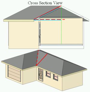
| I've made up another simple model to show how to handle
hip roof sections.
The blue horizontal line in the next picture (Cross Section) represents the width of the roof section in Plan View. When raised to match the pitch of the roof, it is too short. (Dotted blue line) The solid red line showing the 3D Section Width, which is correct, is wider than it would appear in Plan View. (Dashed red line) This is why you use the 3D Cross Section View to determine the Width of the Roof Section. But in this hip roof example we need to cut the 45 degree angle to match up with the adjacent roof section. Dashed red line in Full Overview. Since we let 3DHA do all the math to give us the Roof Section Width, this step becomes very easy. |
|
|
|
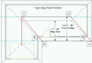
This Plan View shows the black dashed lines of the roof. The outside perimeter lines (facia) and ridges are the correct lengths, but the hips and valleys are 2D and we need 3D. The dashed blue lines represent the size of the material we need. (Width from Cross Section, Length = oversize it at first; more than double length to include material to build opposing roof panel which should be same width) We know that Facia lengths are correct in Plan View, so Points A to B are correct. Place your material on your Plan View (at scale), above Facia AB, aligning right edge with point A, and mark the material at point B. Now move the material below Facia AB, aligning right edge with point A, and mark the top side of the material at point C ridge. Draw a line from point B to C on your material. Use the marks on your material from points A-B to mark the distance from point C to point D. Angle E2 should match angle E. Cut along your lines. This roof section should be complete. |
| The key to this is using the Cross Section Tool to
determine the width of ALL of the roof sections and using the Plan View
to create Ridge offsets!
The ridge to facia relationships (along the same plane) are correct in Plan View and the tough math is done by 3DHA in creating the Cross Section. If you had to do that part, you would be making a calculation that includes the pitch of the roof and the width of the building section. Let's not get into all that geometry. Now you should be able to cut out wall and roof pieces for most models. All you have to do is put the model together. |
Start with a foamboard/foamcore base. Print out your Plan View to scale, piece it together using the indexing marks printed on the pages, and paste it to the base. Use the plan as a guide for placing wall sections. I usually glue two perpendicular walls together first so they can stand up on their own. If you don't want to glue your model to the base, I would suggest using straight pins as a way of nailing the walls to the base temporarily. I generally use white glue, but fast drying glues are available at hobby shops if needed. |
 |
Hip Roofs are difficult to glue up because you have to get the slope of the roof just right during the glue drying time. Use a Cross Section of the area under the roof and then cut out the reverse of the roof. You would create at least two forms represented by the dashed red line in the previous picture. Use two scrap pieces to attach these forms together to use them as a cradle to hold your roof during the drying stage. |