3DHA System Settings

Most of 3DHA's dialog boxes show themselves when you go about making a change to your plan. But the dialog boxes I will be covering here are ones that don't generally show up unless you go looking for them. These are the default values that 3DHA uses when you add objects to your plan. These boxes are included so you can determine, for yourself, how you want 3DHA to work.

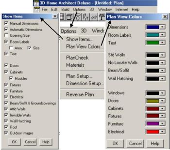
The first dialog box I will cover is the Show Items dialog box, which can be found in the Options Sub-Menu. This is where you can toggle On and Off, different item types that show up in both Plan View and 3D views. This allows you to create views that appear cleaner. For example, if you want a Plan View of the Electrical items as they relate to the structure, you may want to turn off Manual Dimensions, Automatic Dimensions, Cabinets, Modules, Furniture, and others so that the electrical items show up better. After making your printout, you can easily turn these items back on.

The next is Plan View Colors. Remember, this is only to change the colors of item types in Plan View Only! But it does allow you to choose what colors you want to use to represent different items. If you want furniture items in your plans, but you don't want them to show up in such a way as to drown out walls and fixtures, you may want to change their color to something real light.

Next in the Options Sub-Menu is the Plan Setup dialog box. Two items I always set right away are Enable Undo and Enable Fixture/Furniture resize. The undo feature will not always be available, but by setting this to Enable you will be able to take advantage of it whenever possible. Furniture cannot be resized by default upon installing 3DHA. This is done because many furniture items are referenced (named) by their Type and Size. By enabling this feature, you will be able to re-size furniture and fixtures.  But if you enable this feature, always remember that the name of a particular furniture item may not be representative of it's actual size because you may have re-sized it yourself.  Ignore casing for doors windows allows you to place a door or window as close as you want to an adjacent wall without having to use the Control key. I prefer to let 3DHA force me to use the Control key because that makes the door/window casings show up correctly. Restrict camera to Room will cause the 3D views to exclude rooms beyond the room where the view is taken. The Unconnected wall min. length keeps you from inadvertently adding short walls by mistake. I leave it at 18" and change it only if I need to create a wall that is smaller. If you like to scroll the screen using the arrow keys then "Inches scrolled by arrow key" will allow you to set screen movement to something that is comfortable for you.

The Dimensions Set Up screen refers to setting for both Manual and Automatic Dimensions. "Place Numbers Above Line" causes dimension text to be placed above, rather than in the middle of the dimension line. "Allow Dimensions in Eighth Inches" will cause the dimension to show up like 12'6"4. The 4 represents 4/8" (or 1/2"). This will only happen if your "Wall & Opening Snap Unit" is either Unrestricted or Inches (1/8") or less. Interiors walls receive dimension lines that reference off the center of the wall. This can be changed to cause referencing from the surface of the wall by selecting the Surface option button under "Locate Interior Wall Dimensions At".  "Number Height" refers to the font size of the dimensioning text. Walls and Openings (Doors & Windows) will snap to the value that is placed in the Inches Text box under "Wall & Opening Snap Unit". You can set this snap unit to whatever you want or you can turn off snap completely by selecting "Unrestricted".  Snap is where an object only moves in increments defined by the snap unit. If you try to move a door to within 1/2" of where it belongs and your snap unit is 1", then you will not be able to place it correctly. (unless the position you were trying to place the door just happens to coincide with one of the 1" snap unit positions) 

The other place where some default settings are found is in the 3D Sub-Menu. You can set default values in the "Set Up Applied Material View" dialog box and also in the "Default Colors" dialog box.

I'm going to cover the Default Colors dialog box first because it affects the 3D views you always see prior to viewing an Applied Material View. Even though the dialog box title (picture below) says "Plan Default Colors", it is referring to the fact that these colors are the Default 3D view Colors for the currently open Plan. In this case, 1st floor.

 The numbers in each of the text boxes represent the different colored squares in the color pallet to the right. The square in the upper left corner is number 1, upper right is 5, and the square in the lower right corner is number 40. If you change a number for say, "doors" from 6 to 14, then all doors will use the default color of White. (row 3, column 4) This does NOT mean that you cannot change an individual door color once it is placed, but rather that the door will be placed (added) using this default color.

To change one of your available pallet colors, make sure the cursor is in one of the object type text boxes, which should cause the corresponding pallet position (squares) to be selected. Click on the "Adjust Color" button and a color adjustment dialog box will open. You adjust the color by increasing or decreasing the amount of Red, Green, and Blue, as well as the Contrast and Brightness of the color. (Black = 0 Red, 0 Green, 0 Blue and White = 255 Red, 255 Green, And 255 Blue) Once you have changed the color of one of the pallet positions, ALL object types using that same pallet position will change. This should not be a problem as there are 40 available pallet positions and only 25 object types. This example shows each object type uses it's own pallet position (color). If you have multiple objects using the same position and you want only one to change, then place the cursor in that object's text box and change it's position number to one that is not currently being used. Then adjust that color to be what you want.

If you have more than one floor in your plan, you can set the default colors for each floor separately by clicking the button to the right to switch floors.

The settings for Applied Material View will only affect your 3D view when you switch to Applied Material View. The first dialog box you see is the "Applied Material View Set Up". Here you can change the way your colors are rendered by changing the "Color Model" and the "Shading" characteristics. You can also increase or decrease the amount of Ambient Lighting that will be used when your rendering is created. If you click the Backdrop button you will be allowed to change the default background color or Select an Image (.bmp) to be used as the backdrop. 3DHA supplies you with a few backdrops or you can add your own. To add your own backdrop, simply obtain the electronic file you plan to use and copy it into the \BACKDROP sub-directory of your program. (generally C:\Program Files\3DHA3) The file MUST be a bitmap file (.bmp). If you have a .jpg or a .gif file, you will need to use a  graphic design program to convert your file into a bitmap file. You CANNOT simply rename the file! If you have nothing else, use Microsoft paint. Open the .jpg file and Save As....bmp (256 color). The background picture needs to be in multiples of 256 pixels. Explaining aspect ratios and photo modifications fall beyond the scope of this lesson. So if you don't understand these, then I would suggest sticking the the default pictures for now.

Saving Your Defaults

Once you have configured 3DHA's default settings to work like you want, you can save these default settings in a file so that these will always be your default settings each time you open 3DHA to work on a new plan. You will still be able to change the default settings for an individual Plan or Model without affecting your overall default settings. Your default settings for new plans are saved in a file named: PROFILE. The defaults for the first floor are saved in PROFILE.PL1, for the second floor in PROFILE.PL2, etc. When you open 3DHA, these files will be used to determine how your session will work. Now that you know how to get 3DHA's defaults to work for you, you can set those defaults and save the file as PROFILE

This does not mean that you are stuck with these settings. If you have a particular Plan that you want to change many of the object colors in, simply do so.  Just remember that when you save this Plan, you do so under it's Plan name. (Example: myhouse.pl1) Don't save it as PROFILE or all new projects will take on the attributes of this plan. The next time you open this plan it will have all of the settings you saved.